Showing posts with label Design Choices. Show all posts

Sunday, September 3, 2017

Design Refresh!

It has been 3 years sense I last looked at the DC Generator controller board design.  In that time we have accumulated over 1,000 hrs of run-time on our system, and 20x other systems boards have been ‘sent out’  (though I am not sure how many are actually running to be honest).  Over the years I have had a few folks inquire about the design, and if there were any more PCBs left – which I had to say no.  But this winter I want to do a design refresh – bring in the learning from the Alternator Regulator project, and specifically add a CAN connection capability.  CAN (following the OSEnergy open standard) will allow for coordination and cooperation between charging sources, simpler remote panel integration, as well as integration with more modern standards such as SignalK.  Much of the ground work has been put into place, and is being proofed out with the Gen 3 design of the Alternator Regulator.  It is time to refresh the controller its self.

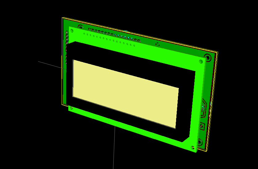
So, here is a 3D rendering of the design I have drafted up:


As before it is a fully integrated engine and alternator controller, with the addition of some additional sensing ports to allow for monitoring of an optional water-maker  (Monitoring for alarm, not active control / automation of the water-maker).  It also includes the aforementioned CAN communications capability.  It does feature a different CPU, the STM32F072, a bit lower cost – but also more programming pace, so the IDE will be a little different (A future project is to see about creating a board-type to support this new CPU under the Arduino IDE).  I have the initial design completed, want to sit on it a while to do desk-reviews, but am looking to make up a prototype this fall, with perhaps a small professionally assembled run later this winter.

Will also be looking at refreshing the optional remote.

A major effort will be bring the firmware up to date.  A major change I want to make is move from include file / compile options for configuring to using the ASCII command approach as on the Alternator Regulator.

OK, this is just kind of a heads up – letting anyone who stumbled across this blog know there is still life in the DC generator project!  If any questions, and if you are perhaps interested in a controller this winter – drop me an Email and/or leave a comment below.

Monday, August 4, 2014

Which CPU can I use for CAN???

With solid requirements a designers job is simpler - choosing the components that meet the needs, at the lowest cost.  But when the requirements are opened ended, it is tougher.  The past few days I have been looking into ways to get CAN and a small micro-controller together, still not sure I have the full answer.

I think 1st I want to limit things to what can be used with the Arduino IDE.   Given the home-brew nature of this project, Arduino's low cost (free) tools, combined with some per-defined wrappers /  libs makes thing a little more easier for a wider range of people.  With this as a framework, I think there are three viable approaches:

1) Use Arduino UNO ATmega328p CPU + MCP2515 CAN controller
2) Use Arduino Due ATSAM3X8EA CPU, it has dual integrated CAN controllers.
3) Use Atmel AT90CAN32 CPU:  A kind of 'grown up' ATmega328 CPU, it has a single integrated CAN controller and  several more I/O ports.
Uno
Option #1 would be the lowest cost ($5.10  using Mouser pricing), and I think I can get all the current controller functionality supported if I shift around some ports and all but eliminate the expansion connector.


Due
Option #2 is perhaps an overkill.  But the two CAN ports could come in useful to support a low-speed and a special low-latency bus.  The ATSAM3X8EA increases program space from 32K to a whopping 512K!  Downside: Cost - $13.51, perhaps a bit higher as I look more into what is truly needed for USB communication.


Something else?
Option #3 is somewhere in the middle.  Its cost is $7.10 - though it does not have the real killer capability as option #2, there are pin compatible versions available which increase the programming space from 32K to 64K and even 128K - for a price of course: $9.00 & $11.33 respectively.


In addition, each of the options will require some extra work in the power supply, and close care with power down modes - as with CAN the controller needs to be alive all the time looking for a call to start generating...


Clearly option #1 is the lowest cost, and its MCP2515 is somewhat supported in the Arduino community.  But I am kind of leaning towards option #3.  Though a little higher cost, it comes with more I/O capability that I could use to provide additional functions w/o an expansion board (ala, controlling external cooling pump & monitoring the watermaker pressures).  Though I could add those capabilities w an expansion board, but the time one purchases the I2C chips, the cost advantage of option #1 is lost.

#2 is such an overkill, and as well as the highest cost.  I also kind of wonder about the future of the Due.  Today I noted two new Arduino offerings, the Treo and the Zero.  Both are high power RISC machines, and I really wonder if the Due's popularity will be effected by them. . . .

Monday, June 9, 2014

Managing Engine Temperature

Not sure why I did not have this before, after all Engines got to be cooled, and we are sampling the engine temperature...  If you engine has a built in thermostat, or temperature controlled fan great.  If not, the I just added an option where the Controller can do that.  A new '#define INC_ET' in your configuration .h file will enable Engine Temperature code, working to keep the engine around the target operating temp as defined in your setup file. (#define ENGINE_TEMP_SETPOINT)

It will utilize the HP Pump FET if that is not already being used to actually control a high pressure Watermaker pump clutch, or a co-gen feature.  In one of those cases, it will instead drive port PB4 as exposed on the ICSP pin#1 in the expansion connector row.  Of course you will need some extra hardware for that.

Right now the logic is simple, turn on the fan when we are approaching the desired temp, and turn it off when we fall below it.  I think a good enhancement will be to add a PID to this, but will need to really think about the tuning values, as well as the sample period.  Given the thermal mass of an engine it is unlikely we will need to sample every 100mS....

Another thing that happens if you enable the Engine Temperature management is the Alternator Pull-back from engine temperate will target 5f higher.  This will allow the cooling fan / pump to do its work before we start pulling back on the alternator.


I plan to use this to control a bypass value placed in parallel with the sea-water side of the heat exchanger.  When enguaged it will open and cut the water flow to the exchanger.  I hope this will help get my engine temp up from its current 160f operating...  Watch for the next release of the Source code v0.1.6 for this feature.  Going to hold off posting it in case I think of some more ideas.


Saturday, June 7, 2014

Monitoring Watermaker Pressures

An addition to v0.1.5 of the Source is a mode for monitoring a watermaker.

Enabled via '#define CHK_WM_SENDERS' this will read pre-filter and High Pressure Pump pressure readings, alarming if they fall out of range while operational.  Example: when running it is important to keep some positive pressure out of the pre-filters and presented to the input of the CAT High Pressure pump.  Failure to do so can cause cavitation inside the CAT pump and potential damage.  As the pre-filters fill up, one needs to keep an eye on them during operation.  I would check them every 30 minutes or so.  But things can change fast.   With this latest addition to the code, the controller will also watch these pressures, display them on the remote LCD panel, and alarm if they fall out of range.

There are two ways to attach senders to the controller, depending on which version of PCB you have.  If you have v0.3.x or above, the SMT Atmel CPU exposes two additional A/D pins, so I simply brought those out as part of an expanded EXPANSION connector.  Add the appropriate resister dividers to get a 0-5v signal and you are good to go.

If you have a v0.1.x or v0.2.x PCB (as I do), then you will need to add an expansion board to get some additional A/D ports.   I selected the PCF8591 I2C chip, it is a self contained 8-bit 4-port A/D converter that can be purchased as a module off of Ebay for very little.  (Or one could make a nice plug-in expansion board with a better fit-n-finish).  Here is an example schematic that could be used as a starting point:


I added code in the read_sensors() function to read the Atmel A/D's ports directly or the I2C expansion PCF8591 A/D converter, depending on which PCB version you have.  Do note which ports to connect which pressure sender to as documented in the source file comments.

A word about reading from the PCF8591: There are several examples out there, most of which make things a bit hard.  The PCF8591 is a rather simple chip - it will do an A/D sampling stashing the results in a register.  When one reads that register a new A/D sample cycle is initiated; you can retrieve the new A/D reading next time you read the register.  Most Arduino example sources do two reads, throwing away the 1st value.  The REAL reason for this is:  At Power-up the PCF8591 places a 0x80 into all the registers.  So, after Power-up the 1st read is of no value.  Added to that there is the issue that when you do read a value out you are really getting the results of the PRIOR A/D cycle, not what is happening right-now.  For this project sensors are sampled every 100mS, so I am not too worried about getting RIGHT NOW vs. 100mS ago.  I also use a mode called Auto-increment: when I read a port the next I2C read will automatically return the next port.  Making for nice simple short code and eliminating unneeded  I2C bus traffic.   OK, a bit of detail, but when doing research I noted folks doing this dbl read and it seemed no one really explained (or knew??) why...


Posted source code release v0.1.5

Today I posted source code release v0.1.5 to the links above (Source-code tab).  This is a rather small release with a couple of big changes.

Perhaps the biggest change is I have broken the single source file into a .ino and a separate .h file. In the SECR_config.h file are all the customization parameters needed for YOUR system installation. The idea is that with future releases of the source you will be able to cope on the new Souce - keeping your same .h file.


With the  SERC_config.h you can:
  • Set some clues about the controller hardware you are using (ala, which version of TLEs, do you have the new FET drivers which need the charge pump PWM - v0.3.x and above)...   
  • Decide which features you want enabled:  Do you have a watermaker to support?  Perhaps instead doing co-gen and want to start a pump at a set temperature?
  • Set checks / probes you have installed:  Want to check the Oil Pressure?   Raw Water Flow (marine installation)?
These are all deselected / selected via commenting out / uncommenting in different #define's.  You will also want to set:
  • Alarm limits for your system, temperatures, volts, etc.  What do you want the controller to monitor and at what threshold do you want it to sound the alarm and shut things down.
  • Engine management timings:  A number of things are done open-loop and for those there are timing values.  Example, before starting we need to advance the throttle cable some to the 'start' position.  Because there is no position sensor on the throttle cable we simple 'advance' it for a fixed amount of time to get it 'about' where we want it.  This fixed amount of time is set by the #define THROTTLE_TO_IDLE_DELAY value.  On my little Kubota 1300 (1.3 seconds) of 'advancing' is 'about right'.
  • Engine management thresholds:  Another group of values are measured thresholds - ones where we have a sensor and can get feedback.  Examples include all the alarm values (Overtemp, under oil pressure) as well as things like:  #define STARTED_AMPS_THRESH which is used to help decide when the engine has started by a drop in measured starter amps.
  • Engine RPM/HP specs:  A key configuration is how much HP the engine is specified to produce at a given RPM.  This is used to limit the max load on the engine; while getting the most out of any running time.  It is also used to decide the throttle position needed, allowing the engine to be slowed down towards the end of the charging cycle with active throttle management.  This key table is called: RPM_Watts_array
  • Alternator and Battery management:  What are your target voltages?  At what point do you consider the battery fully charged?  Do you want to move on into Float Mode of stop the engine when the battery is fully charged?
  • The address for all the DS18s20 temperature senders need to be typed in, see the assembly tab above for some hints on how to determine these values.
  • You will also want to set other misc parameters, such as the engine and alternator pulley size - to calibrate the measured RPMs.
  • And finally, configuration of AutoStart mode can  be done.  Do you want the generator to auto-start when the battery reaches a specific voltage?  There is more to do in this area, ala setting block-out times via the RTC on the remote.  But this is a start.


Configuring the .h file will take some time; take care in setting this up making sure not to choose more then one option, and also pay special attention to how values are defined.  e.g., many of the timing values end in UL, you need to make sure to retain that Unsigned Long guidance for the compiler.   Once set up you might have to tweek some settings to fine tune things, but after that things should go smoother when loading new revisions to the source.


Finally:  Need to point out:  as I am away from the boat these days (See Viking Star blog) I have no way to testing this release outside of bench testing.  Version 0.1.3 (also on the source-code tab above) is the last version of source I had actually loaded into our DC generator.  This August I will be back at the boat for a check-in and will be able to verify newer releases in actual hardware.


Tuesday, June 3, 2014

Breaking the Engine, wait - no ---

-- that's Breaking-in the engine!

At a suggestion, I added a new #define:

#define BREAKIN_ENGINE  

the idea is to adjust the controller in ways that will help the engine during its first few hours of operation.  Kind of like a new car cautioning you to not go above 70 MPHs, or use more then half throttle for the first 300 miles (or what-every they say these days in new cards).


To enable the Breaking-in mode, uncomment the above #define in the configuration .h file.   So far the behaviour changes I have are limited:
  • Reduce engine load to 50% of its capability at all RPMs
  • Prevent co-operation of Alternator and Water-maker, only power one or the other.

This is a compile / flash option, perhaps down the road I will work harder on the remote module to perhaps allow more configuration via the remote vs. having the re-compile each time.  But that will be down the road some...


Look for this new capability when I post the next revision of Source.  And if you have any ideas of other limits to add, please let me know..


Monday, May 26, 2014

Driving two alternators -

I was asked about the ability to drive two alternators on one engine and charging one one battery bank.  Here is what I replied:


Driving two alternators.  There is a massive capability in the Field FET driver ckt.   Each FET has an Rds of only 8 mOhms, and is base rated for 80A.  I used two in parallel just because they are not that expensive and two will assure a massive current capability with very little heat.  I think the biggest limitation is the current capability of the PCB, even with large copper areas.  If you note I am leaving a gap in the solder-mask on the top and bottom from the Field connectors to the FETs.  On this one can solder heavy wires (like 16g or even 14g solid) to increase the current capabilities of the copper PCB.   For two alternators I would suggest you do that to beef up the PCB.

Then I would simply wire the alternators in parallel.   If they are the same type / model there will be some level of current mismatch between the two, but not sure that really matters too much.  I just now thought:  there is a spare temperature probe connector on the PCB, you could use that to monitor the temp on the 2nd alt.  I will modify the code to sample both alts temps when deciding if things need to be backed off.  But as long as you do not need abs matching, I think just drive them in parallel…  

If one is much larger than the other, the miss-match could become large.  For example if you had a 200A and a 100A, perhaps the small guy will drive harder for a given field PWM setting.  In that case we could be driving the stuffing’s out of the small guy while the big one loafs along.   You could measure the current of each with a clamp-on amp meter and if you need to pull back the little guy some just add in a couple of diodes into the field for the small guy, to drop its field voltage and try to bring things more back in line.  (ala, thinking at any given PWM drive level you would want to have the Amps out of each alt be at about the same % of their respective max capability.  If you have a 200A and a 100A alt, then when delivering 150A into the battery you would want the alts delivering 100A and 50A respectively.  Not say 60A and 90A -  thereby working the small guy so much harder).

Hope this makes sense.  In short, I think all you need to do is add the copper beef-bars to the PCB, connect the Alts in parallel, connect up a 2nd temp probe to the 2nd alt.  Then check with a clamp-on amp meter to see if the load splitting between the two seems reasonable.


======================================================================

Today I modified the code adding in a spot for a 2nd alternator temperature sensor.  To enable it you just need to add in the address of the one-wire probe in the source:
#define OW_ALT2_TEMP    {0x00, 0x00, 0x00, 0x00, 0x00, 0x00, 0x00, 0x00}
                                             // 2nd Alternator Temp (if present)

Note that by default I have this filled with zeros, in effect disabling that temp probe.

In operation the code will look at both alternator temperatures and pick the hottest one to 'manage' things with.  I have not added anything into the LCD display for the 2nd probe, need to figure out where to put that at...


Sunday, May 25, 2014

1st cut - moving to SMT; getting ready for a short assembly run.

Last week I was busy revising the controller design and moving it to SMT parts.  This is in preparation to having a small run of boards made up, and then machine assemble a large part of it.  Major changes to the design include:

  • Utilized universal Field driver ckt to support 12v-48v, P or N type alternators.  No more need for stuffing options.
  • Also updated the FET drivers for things like starter, glow plug, etc to remove the need for stuffing options.
    Power supply now stuffing free as well 
  • Moved most of the components to SMT, and selected parts from the standard pool of parts at Smart-proto

Overall, most everything has been touched and/or refreshed. The PCB is smaller now, 15x15cm to match a ‘price break’ size for may PCB fab housed.  I looked into going to 15x10cm, but just ran out of edge space for all the connectors… Moving to SMT will allow China to not only manufacture the PCBs, but also do machine assemble of as much as possible. Will decide about hand-soldering through-hole components based on the outcome of the regulators, but it is not too promising IMHO.

Here are three CAD 3D renderings of the PCBs as they are now.


Biggest change: controller board.  Now mostly SMT, except the high power parts.


SO much blank space.  PCB is 15 x 15cm.  I looked into squeezing it more, to perhaps 15 x 10cm, but just ran out of edge space for all the connectors.  SMT stuff is amazing; I even tried to select somewhat 'larger' parts in case repairs, or handwork is needed.  Even so - - - -


Only change for the remote is in the Power Supply side, to match the controller


Notice how the PCB has been sized to match the LCD, no more overhang!


For now I left the remote panel as through hole.  There is only one part that likely will be SMT, as the DIP-8 versions are getting hard to find.  This would mean you would need to solder up the remote yourselves, all the parts as opposed to just a few.  My thinking is:  There really are not many more components that can be put into SMT, the CPU, about a dozen resisters and diodes;  it might not be worth the extra setup costs just for those.

I want to take a break over this weekend from this, and then do a review of the design as well as the PCB layout next week before releasing the revised schematic to the blog.  One thing I need to double check is the heat disbursement;  the SMTs are much smaller in that regard and I need to make sure I am not over-burdening anything.

There is now people interested in 8x of these controller boards, we are looking to do a small PCB run + machine assemble of the SMT parts.   If you are at all interested in joining, drop me an Email.  I figure things will get moving perhaps mid June.

Saturday, May 24, 2014

P-FET driver using Constant Current source

One of the challenges I faced with this controller project was being able to support both a 12v and a 24v 'system' voltage (starters, fuel pumps, etc).  For simplicity I wanted to use a Active High output for these devices, that is to say when the fuel pump was 'turned on', +12v (or +24v) would be supplied to that connector pin.

A simple way to accomplish this was to use a P-FET, but the problem comes into how to drive it, esp as in the 24v system we could easily exceed any Vgs limit if not careful.  In prior version of the controller I accomplished this using a simple NPN transistor and pull-up resisters, then added in stuffing options for a resister divider to handle the 12v or 24v configurations.  With through-hole parts, selecting (or even changing) a single resister to match the system voltage was not too bad.  But with really small SMT parts. . .

So, I came up with a new approach for driving the P-FETs.  Still using a simple NPN transistor + pull up resister (these signals are just on/off, no real concern about Ton or Toff transition times), but this time I created a constant-current source out of the NPN, thereby eliminating the need for any voltage-divider resister:


R39 is driven directly by an Arduino port; when driven HIGH it will turn on the LED D24, as well as Q11.  Taking advantage of the relatively stable voltage curve of LEDs I end up with a rather stable voltage at Vb of Q11.  (Around 2.0 to 2.4v). With a constant voltage at its base, Q11 + the emitter resister R45 forms a constant current source.  Doing the calculations comes up with around a 5mA CC source out of Q11 that is then used to pull down the FET's Gate through R38.  D33 starts conducting once we reach 15v max Gate drive, keeping us well under the Vgs limit on FET Q14.

And as a bonus, I get a 'free' indicator LED I can use to tell when a given port is being driven!

This design models out in SPICE as being stable from 5v (about the min turn on for FET Q14), up to 40v.  The limiting factor being we are now dumping power in Q11 as opposed to an external resistor - so Q11 becomes the critical limit.  Depending on the LED selected, and its voltage curve, you may have to play with the emitter resistor R45, making is smaller or larger until arriving at the desired constant current source value. Once locked in, it will not very much as the LED drifts some.  And the zener diode can be adjusted to match the specs for your FET.  If you have more headroom on the Vgs, D33 can be increased - resulting in less power needing to be dumped by Q11.  I will likely increase D33 from 10v to 15v in the final design, that will reduce Pd in Q11 from 150mW at 40v down to 120mW.  Depending on the final FET selected for Q14, might even be able to use a 20v zener!


Thursday, February 20, 2014

v0.1.4 of source code posted

As promised, I have made a small change to the source to support either the INA-220 or the INA-226 chip.  These are pin compatible chips, and either CAN be used, though the INA-226 is an improved chip.

If you are doing a 12v system, either will be fine.  As with a 24v system (though to support 24v, the INA-220 will need some pre-scaling divider resisters, which the INA-226 can support a 24v system directly).  For 26/48v, the higher native voltage of the INA-226 (36v vs. 28v), plus its higher input impedance makes for a slightly more stable and accurate measurement chip.

You can read a bit more about this here: SmartDCgenerator.blogspot.com/....improved-voltage-sensing-chip

Now, a WORD OF CAUTION:   Because I am away from the boat these days, I have NOT BEEN ABLE TO TEST THIS CODE ON ACTUAL HARDWARE!!!   As such, I left the prior version (v0.1.3) on the google drive as well as the new v0.1.4 version.

Also note that I revised the order of the parameters for the #define AMP_SHUNT definition, from mv/Amps to Amps/mV


Saturday, October 19, 2013

Improved Voltage sensing chip?

Over the summer I have been working not only on refinements to this integrated engine controller and alternator regulator firmware, but have also been working on the stand-along alternator regulator project (arduinoalternatorregulator.blogspot.com/).  One of the goals of the standalone regulator was to self-adjust for 12v up to 48v batteries.  After I finish the stand-alone regulator I will be taking all the learning’s and rolling them back into the integrated controller, but there is one learning that I think would be appropriate to share today…

The INA-220 is a great chip, and core to these designs.  It also is limited to 28v max.  As such, to use it for any system greater then 24v divider resisters are needed to pre-scale VBat (and even 24v batteries can exceed this limit during equalization).  What I found out over the summer is the input impedance of the INA-220 is not that stable from part to part, and is also rather low.  As such the resister divider network tends to introduce a wider range of error that I would like – errors that delta from part to part.

Fortunately, TI now offers an upgraded part called the INA-226.  This is pin compatible to the INA-220 and has much better input impedance characteristics – both higher and better controlled.  And more interesting, it is tolerant up to 36v natively!   So, this means that NO pre-scaling will be needed for 12v or 24v systems, even during equalization on 24v batteries.


So if anyone is looking to do a 24v or 48v system you might want to look to upgrade the INA-220s to INA-226s.   It will give you much more accurate results as well as reduce the need to ‘fine tune’ adjustment factors.  (and 24v systems will need no resistor divider at all)  There is a firmware change needed as the new parts have a slightly different register layout; I have some parts on order and will be updating the firmware over the next couple of months.


Sunday, October 6, 2013

v0.1.3 of source code posted

Today I posted V0.1.3 of the source code.   Over the summer I have been fine tuning the controller, looking at the PID for managing of watts and more specifically how it handles temperature limits, added a couple of new operating modes and a true load-dump trap.  Changes include:

  • Corrected bugs in LOCKOUT mode.
  • PID tuning for Amps and Temperature PID engines.
  • Two new modes:  Quiet Generating, and Prime Oil Pressure
  • Load Dump trap (based on rate of change of Voltage vs. time)
  • Self-learning wattage caps when over temperature situations are detected
  • new #define TESTING that allows for limited bench-testing w/o generator
You can see the new source code via the SOURCE link above. I also posted v0.0.2 of the integrated remote source code which is needed in order to select Quiet Generation mode from the remote.  You can still use v0.0.1 of the remote code (or even the original non-Arduino based LCD remote design), you just will not be able to place the generator into Quiet Mode.

Perhaps the  biggest change is on how over temperature limits are handled.   In addition to doing some tuning of the PID engine (mostly around EGT limits), I also added in code that will learn from over temperature conditions and reduce the maximum load placed on the engine.  This is to prevent the over temperature situations from happening again.  It also removes an interaction between the Watts PID and the Temperature PID.   (I 1st noticed this happening when EGT limits were exceeded.  The EGT PID would pull things back till the engine cooled at which time the Watts PID would say - OK, lets Go Hard Again!!).   Watts Pullback is enabled for all three of the temperature limits (EGT, Engine, and Alt), but the EGT is the temperate most likely to walk the the line,.  This is to be expected as a key goal of this project was to minimize total run time by maximizing the load on the engine at all times. So, I added code to pull-back the target watts whenever a temperature limit is reached.   And this pullback is self learning, resetting itself each time the generator is restarted.

Quiet Mode is a new mode that simply limits the engine RPMs to a defined maximum (with the appropriate reduction in watts to match the lower engine power output).  Allowing 'quieter / gentler' running - suitable for those times when running Full Out is not appropriate.   With the new remote LCD code, Quiet mode is selected by pressing AND HOLDING the Run-Gen switch for 3 or more seconds.  And you can toggle in / out of Quiet Mode by simply pressing the Run-Gen switch to get back to Full Power;  pressing and holding it to get back into Quiet mode.


Prime Oil Pressure will enable the starter but NOT the fuel.   It will turn the starter while monitoring the Oil Pressure gauge waiting for the Oil pressure to come up.  (Starter is spun in the same pattern as during regular starting - currently defined as a max of 5 seconds, the a 4 seconds rest period.  repeated a up to 4 times - See source code to change these values).   It can be used to 'prime up' the engine oil system after changing oil.   Currently the only way to select this mode is via an attached debug terminal.

I added in code to specifically look for a load-dump condition.  While debugging the stand-alone voltage regulator I found the PID engine alone was not sufficiently quick to rein in large alternators (ala the 270A monster I have on our mains vs. the 135A one of the generator) where there was a massive reduction in load on the overall system.  For example, when the heating element on the dryer cycled off and the battery was almost fully charged (and hence the battery voltage was at its target) I could see a voltage overshoot approaching 450mV (almost 1/2 a volt).  I added in code to not only more aggressively reduce the PWM if a voltage overshoot condition occurs, but more importantly try to prevent it in the 1st place by looking at the rate of change of voltage over time (dV/dT).  Using both these approaches I am able to contain load-dump overvoltages to 35mV above target.  


And finally I placed in a #define TESTING switch.  Enabling this will dummy-up key sensing (ala battery voltage,  alt amps, EGT, etc..) to allow for a level of bench-testing of the code on a stand-alone Arduino development board.   It is some of the early mock-up code I had in there before I had real hardware, and I find it useful when doing things like adding new modes of operation (ala Quiet mode) to be able to 'test' things out before trying it out on real hardware.   But DANGER:  MAKE SURE #TESTING IS NEVER DOWNLOADED TO A REAL GENERATOR, as all the sensors are dummied up, and hence you run the massive risk of really doing bad things!!


OK, so, some small improvements.   We now have 100's hours on the system now, in generate mode as well as watermaker/generate mode.   And I am still very happy with how it is working!


Thursday, September 12, 2013

Transfer of Technology - Load Dump

This summer I have been working on a Stand Alone - Alternator Regulator only project.  Built upon this DC Generator code, it removes all the engine control logic while retaining the monitoring of Volts AND amps - and is an open source /  Arduino code base  as well!

One of the benefits of this Regulator Only project is being able to back-port improvements to the DC Generator design.  A prime example is Load Dump - though with my smallish Alternator the PID logic was able to handle Load Dump situations in the DC generator, PID was not fast enough for rein-in larger alternators.  Ala, the 270A one on Viking Stars main engine.  

So, today I improved the regulator code adding in Load Dump detection and associated Field PWM pullbacks.

And you can be sure this code will make its way into the DC Generator's code base - just as appropriate changes in the DC generator source are ported into the stand alone regulator code base.

To learn more about Load Dump and how I addressed it - click here:  arduinoalternatorregulator.blogspot.com/2013/09/looking-at-load-dump.html


Wednesday, May 8, 2013

ARG - DIP vs SMT...

It has been quiet here on the blog for the past couple of weeks.  That is largely due to two reasons:

  1. Sun is coming out and our Solar Panels have been keeping up with power demands - as such I have not been running the generator, and do not have much opportunity to find Faults.
  2. I have been working on a Alternator Only design.

The Alternator Only design will be based on the core of this controller, but without any of the engine control features.  Just manage the Alternator.  Am still targeting support for 12v to 48v batteries, as well as P and N type alternators.  But adding a couple of new ideas:
  • Ability to intelligently connect two together, for use in twin engine deployments where they are charging the same battery.
  • Perhaps a simpler UI, using DIP switches to select a defined set of profiles (or a custom one), even looking into using one of the arduino to PC communication tools for a more GUI interface (as opposed to the current debug text stream).
Have finished the hardware design (1st pass), and one of the issues I keep running across is the quick disappearance of DIP components.  Everything has moved to SMT, and it makes selecting easy-to-solder DIP parts tuff.  Either the part is not available (ala the INA-220's), or not stocked (which I just found out on the P82B96 buffers from Mouser), or are 2x the cost...

Arg. . . .

Perhaps will just need to bite the bullet and accept that some of these components will always be SMT.  It is the way of the future!

Update 6/14/2013:  And it just keeps getting worst.  It seems the P82B96 I2C buffers I am using have been dropped in DIP package from one supplier... They are available from TI, at TWICE the costs!   Arg.  Have modified the PCB layout to accept BOTH an easy-to-solder DIP, and not as easy SO-8 package.   If I need to move to SMT, at least I can stay away from those really small packages....


Sunday, March 24, 2013

Posted KiCAD design files

Given the current status of the project, I posted the KiCAD files today.   The version posted is 0.2.4, and it differs from the v0.2.3 PCB fabs in:
  • Added R60 / R61, to be used in conjunction with a TLE5206-2 bridge.  (See source code)
  • Modified some of the part numbers, ala using Male headers instead of Female for SERVICE (Lower cost).  That will require you to purchase only one $$$ female header and solder it to the USB <--> TTL converter.
  • Added part numbers for switches I used in combination with the custom front panel
See CAD-Files tab above.

It should be noted that as of yet, none of the v0.2.3 PCBs have actually been assembled.  If (when) problems are found over the coming weeks / months I will update the CAD files, but will likely not be doing careful revision control...

If you want to use these for your own project, the are released under the same licencing terms as the source: 
    Creative Commons Attribution-NonCommercial-ShareAlike 3.0 license 

And idea beyond that, contact me.

And if you do find issues or enhancements  please drop me a line.  I likely will maintain the CAD files for a while and would be grateful to be able to roll in any improvements / corrections.


Sunday, March 10, 2013

Measuring RPMs from Stator - while not charging...

I sample the Stator signal -  feeding it into an IRQ. The primary reason for this it to synchronize the INA-220 sampling cycle to be in lock step with Stator pulses (Best practice for measuring voltages it seems), but I also use this to determine the Alternators (and derive the engines) RPMs.

This approach for measuring RPMs works very well when we are charging.  However, when the Field is dropped to zero the Stator interrupts  go away and we are all of a sudden 'driving Blind' when it comes to managing the throttle.  Some alternator regulators have a 'Tech' mode that will always apply some small level of field voltage, just enough to allow for enough stator signal to sample RPMs.  Used primary on Diesel engine it does come with a warning that 'extended use' could cause battery overcharging.

Today I went back over the 20 or so Live Run data sets I have collected, looking at when RPMs measurement appears to become stable, and then Amps actually being delivered.  And there seems to be a rather solid pattern:

  • A PWM of 2 in all runs (one needed 4) gave sufficient signal to allow for stable RPMs measurement,
  • Amperage does not start to be delivered until PWM values of upper 40's (and some times into the 60's).
It was interesting that in all cases RPMs could be sampled with a very low PWM value..  Very low.  And given that actual charging does not appear to start until PWM values of near 50 or greater, there is LOTs of margin.

Now, I also noticed a curious situation in 1/2 the runs.  All runs (with out exception) started given solid RPMs at 2-4, but in about 1/2 of the runs the RPMs became unstable when the PWM value reached the mid to upper 20's.  In fact, the indicated RPMs would drop to 0 until the PWM value had climbed into the  40's when they would again become stable.  Amps would start to be delivered when the PWM  raised another 10 or so.  

Some time I will put a scope to the system and see if I can figure out what is happening during this Blank Period.  But until then, my walk away is:
  • We can safely send a small Field PWM value to the alternator to allow for RPM measurements without worry of overcharging the battery.

In MY system, a PWM value of 5 or so looks to be gold.   On other systems one would likely want to verify this number by looking at the DEBUG logs of a few live runs.  But given the above I am going to modify the source to allow for all-the-time RPM measurements   This will mostly help while starting, as well as when stopping.  (Currently stopping runs blind, making a nice slowdown of the motor a little difficult to prevent entering a to-slow situation before fully cutting the throttle).

Of course the PWM value will be selectable, and I will have a way to disable this capability of one wishes.


Saturday, March 2, 2013

Going integrated!

A problem with the v0.1.3 PCBs is the misalignment of the Remote PCB mounting holes and the attached LCD. I have made a small 'adapter' out of some scrap fiberglass panel, and repositioned the holes in V0.2.x of the PCBs.   However, over the last week I have been playing with the idea of a redesign which directly talks to the LCD module, as opposed to via the PIC based 'back pack' of the current approach.


Here is a snapshot of the revised design which uses an Amtel CPU to receive the I2C commands, monitor the key-buttons, as well as drive the LCD.  There are plunty of Arduino modules out there to use as building blocks, for the LCD, the keypads, and the I2C in Slave Mode.


Notice how it is just a bit larger then the LCD itself


I have ordered a PCB via Batch-PCB, and the parts from Mouser.  Will take over a month for them all to come in, and I expect to be playing with this over the summer.  Until then, will be just using the current 'Back Pack' v0.1.3 PCB and design.

But, this could be yet another fun project!


Thursday, February 14, 2013

High Drive, Low Drive? Maybe Both Drive!

I have wrestling with the High vs. Low driver perhaps more then any other design choice in this project.  Originally settling on High Drive as the while world seems to do that (and i still have not find the 'reason' why).  But it is true that many alternators which are configured for external regulators are set up for a High drive.

And then there is the point that using High drive means the Field voltage needs to be lock stepped with the controller voltage.  (without some really wild effort).  And more so, many of the FET drivers are limited to a 24v system.   So, there is a REALLY good reason for doing low drive.

.. Except the rest of the world is high drive.

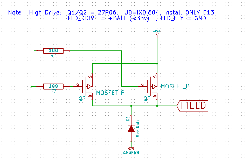
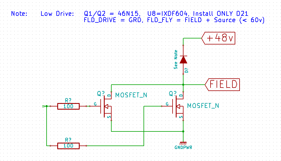
So, I have been playing with the possibility of doing a You Pick Drive, w/o using different PCBs and major solder jumpers.  And I think I have it.  By careful layout of the PCB, and selective part stuffing / choice I think we can have a configurable High or Low Drive.  All one needs is an extra connector pin, and then a N or P FET is chosen at build time (Plus the driver version, and where to put the snubber diode).  Here is what I have:


When stuffing the PCB U8, Q1, Q2 and D13/D21 are selected per the note.   Then the appropriate voltages are passed into FLD-DRIVE and FLD_FLY.  

Here is how it would look configured for High and Low Drive.  I did 'CAD' things around a little bit to make each configuration more like what one would expect.  But if you follow the traces you will see it is really the same as the one above.

Configured for High Drive


Configured for Low Drive


What makes this workable is that the P and N FETs keep the same 'pins' for D, G,  and S.  And it so happens that  D always connects to the Field, and S always connect to the voltage that the non-driven end of the Field  (the end back on the alternator) is not.    I did loose one snubbing diode, but it was rather of an overkill - one only really needs the one across the Field coil, not an extra one across the FET.


OK, so this is how I am going to revise the PCB.  Then it is up to the builder - High Drive or Low Drive...


Sunday, January 27, 2013

Low Drive Adapter for v 0.1.3 Controller board

This morning I did a quick design of a daughter board that can be used to adapt the current HIGH drive controller board (ver 0.1.3)  to a LOW drive.  The reason one might want to do this is to be able to control alternators which use a different field voltage then the other components.  e.g.:  a 48v alternator with a 12v starter, fuel pump, etc. is used.

Just mount this to a heat sink and connect the appropriate wires.   And this, btw, is the final drive that I am revising the PCB artwork to.  Not only is it low drive, but I also selected higher voltage FETs.  Note the new wire:  Flyback - connect this wire to the + side of your field to allow for the clamping diode to work.


Friday, January 25, 2013

Looking at the +5v regulator

(revised 1/26/2013)

Currently a LM2575 switching regulator is used for the +5 feed.  I had selected that  primarily for the efficiency vs. lost energy of a simpler liner regulator, but also because I wanted to play some with Switching regulators.

In a recent review, someone (who has given great input over the past months) suggest using a simple liner regulator would be a better choice: simpler/lower noise, lower cost, and the loss would not be that great.  So lets look at each of those points, and hang on - it Math is going to be involved :-)

Simpler:  No question here.  Replacing the larger filter capacitors  L1, D7 and the regulator its self with a couple of small caps and a 79R05 regulator would be simpler and more straight forward.  The the approach of using the 9V regulator at the 1st set, followed by a 7805 regulator would be even simpler.  And no issues with switching noise begin introduced esp around the INA-220's.

Cost: The current LM2575 approach included BOM parts that totaled: $6.14, while repositioning the 9V regulator and adding in a 7805 would cost $1.03 with its associated capacitors.  Add in another $1.58 for a reasonable heat sink (e.g. Wakefield 657-15ABPN) and we are up to $2.61, or a BOM savings of $3.53   Not world changing, but $3.50 is a notable amount.

Loss:  Here we are talking about efficiency of the conversion, and how to handle the wasted heat.  During simulated trial runs the controller board had up to a 26mA draw at 5v depending on the phase.  (less when Idle, more when actively managing the field and throttle).

Lets look at the heat load of using a 2-stage cascaded liner regulator approach:  Battery voltage to the 9V regulator, and then 9V to the 5V regulator. Cascaded to spread the total heat load over the two regulators, plus by using this approach we leverage the on/off capability of the 78R09 regulator and are able to use a lower cost 7805 in the 2nd stage.

Using this liner approach the battery feed would require the same 26mA current.  Looking to worst case battery voltage:  16V giving the 1st regulator 16-9v = 7v drop at say 35mA (for some margin)  = 245mW to dissipate as heat.

OK, lets get into more math.  Two key parameters to know are the 'thermal resistance' of the 78R09 regulator and the heat sink.

For the regulator the Junction to Case resistance is: Ro-jc = 4.31C/w
For a reasonable heat sink (1"x1"x1.5") the resistance is:  3.3C/w

For a combined thermal rise of:  7.61C/w.   At 245mW we get a bit under a 2c rise.  Selecting a high limit operating temperature of 120f (50c) results in a 52c junction temperate.  No issues.

But now, lets consider operating in a 24v environment   Here we will swap out the 9V regulator for a 15v one and assume a VBat max of 32v resulting in 456mW to dissipate.  Running through the same as above gives a 3.5c rise resulting on Tj = 53.5c junction temp.  Again, no issues.

Bottom Line:  Doing cascaded liner regulators would work fine for a 12v  or 24v system.  In fact, even in a 24v 'system' the 15V  1st stage regulator would only see a Tj of 77c without any heatsink!  (using Ro-ja =  48.83 for free-air operation).  Placing it down on a PCB heat-sink pad area should work just fine.