The project is based on the Arduino one board development environment
The hardware is broken down into the following major sections:
- CPU and support + expansion **
- Kubota Engine Control
- Alternator Interface
- Serial Buses (I2C and ONE-WIRE)
- Voltage and Current Measurement
- Temperature Sensing
- Local control switches **
- Power Supplies
- Remote Panel **
CPU and support + expansion
Originally I had though to build a 'shield' for the Arduio line of development boards, but as the project grew it became apparent that the actual CPU hardware contained on the Arduino cards would be a very small portion of the project. Adding an Amtel CPU and its supportive logic was a very small step. Plus it eliminates a potetnial failure point (the connectors).
The ATMEG328 CPU is placed directly into the board, along with its 20Mhz crystial. I repliacted the standard ICSP connector from the Arduino design, to allow for the loading of the low level So I placed the Arduino programming environment into the Amtel CPU. I also routed unused pins, along with the I2C and OneWire bus to a connector called Expansion. By placing these two connectors in line with each other on the PCB, it might be a way to expand the current Kubota Engine and Alternator control logic to include the Watermaker...
One place I departed from the Arduino design was in the USB connector. Rather then have it down on the board I brought the pins out to an inline connector (labeled SERVICE) where a low cost USB - Serial adapter board can be used when needed. I did this to eliminate an exposed USB connector, and perhaps to lower the cost some.
The final connector (BLUE-TOOTH) is an experiment I am thinking I might be able to connect a low cost Blue-tooth transmitter here and perhaps be able to do some wireless modifications of the firmware, or perhaps use it to connect a more advanced terminal via the PC. This part I have less then positive feeling about and we will have to see how it comes out.

Kubota Engine Control
One of the major functions of this project (at least in the Feature Creep mode) is being able to monitor and control the Kubota Engine. We need to be able to enable the starter, pre-heater, fuel pump as well as control the throttle. For the Fuel Pump and Pre-heater I selected simple FET +12v drivers: |
| Representative FET high level (+12v) driver |
Due to a larger expected current draw of the starter solenoid I decided to use a grounding output which should be used to drive an external relay that can then drive the starter solenoid.
 |
| Representative FET low level (GND) driver |
Using a simple N-Channel FET. the 1K resistor provides some isolation between the Avtel controller and the FET, while the 10K resistor is intended to make sure the FET remains disabled during cold-booting - before the program has configured the Avtel ports for output. Again the SB550 Diode provides back-current spikes that might occur from any inductive load. And note I selected a Logic level version of the FET. This raises the Von switching voltage a little and gives a bit better noise margin from accidental turn-ons before the Avtel ports are configured.
For the throttle control I am looking to reuse an automobile ‘Cruise Control’ drive module. I had thought about using a stepper motor, but felt the automobile cruse control had the advantage of being already mounted and designed for wet locations along with a wide temperate range. Plus, they are readily available and cheap.
The unit I selected came from a 1990 Integra. Looking at the wiring diagram we can see there are three control wires: Clutch, Accelerate and Decelerate. These last two control a reversible DC motor that will pull in or relax the throttle control cable. Note there are built in limit switches. Disabling the clutch releases the pull-in cable and lets the springs on the Kubota throttle move the lever to the Full Stop position. Enabling the clutch we can start advancing the control cable all the way to Full Throttle position where the Acceleration limit switch will stop any additional moment This gives me the basic All or None control over the Kubota. A more advanced design will adjust the speed of the Kubota engine, monitoring the RPMs via the Alternator Field signal.
The unit I selected came from a 1990 Integra. Looking at the wiring diagram we can see there are three control wires: Clutch, Accelerate and Decelerate. These last two control a reversible DC motor that will pull in or relax the throttle control cable. Note there are built in limit switches. Disabling the clutch releases the pull-in cable and lets the springs on the Kubota throttle move the lever to the Full Stop position. Enabling the clutch we can start advancing the control cable all the way to Full Throttle position where the Acceleration limit switch will stop any additional moment This gives me the basic All or None control over the Kubota. A more advanced design will adjust the speed of the Kubota engine, monitoring the RPMs via the Alternator Field signal.


In order to drive the Cruise Control unit I am using an H-bridge. Through one could be built using discrete components, I selected an already integrated unit the TLE5205-2. It is rather expensive (Almost $5!), however its cost is in line with what would be required to assemble an H-Bridge using discrete FETs. Plus, there is less board space needed. The TLE5205-2 is rather self contained, with no external bypass diodes needed. The TLE5205 is able to drive 5A and as such should be adaptable to any automobile cruise control selected.

Reading app notes and white papers for regulators used in automobiles turned up an insight that WHEN sampling the voltage is just as critical as HOW it is sampled. Specifically, it is best to lock-step your samples with the stator peaks. So a stator sample line was brought into the Atmel INT0 pin and will be used to synchronize sampling.
To do this I sample the Stator and use it to trigger an interrupt into the Amtel controller which can then initiate a sample cycle in the INA220s for voltage and current. The raw stator is ran through a 2:1 voltage divider and the integrator (C18) and finally clipped by D14. Driving IRQ-0 pin on the Amtel we will enable an interrupt on the raising edge of the stator voltage.
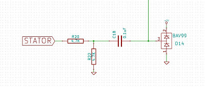
NOTE: <2-10-2013> The design has been modified --> R20 was changed to 1K, R22 was replaced with a 0.1uF cap, and C18 was removed and a jumper wire put in its place. This is very stable now.
By measuring the time between interrupts I am also able to gauge the RPMs of the Kubota engine. This can be used for more advanced charging approaches (e.g., matching the engine speed to charging demands – slowing it down when charging demands are light). It is also used to detect overload conditions and perhaps as part of the Kubota start program - to decide when to disengage the starter.
Alternator Interface
There are three connections to the Alternator:
- Field Control
- Stator Sensing,
- Alternator Temperature. Temperature is handled in the Temperature section (below).
For the Field control I went back and forth between Low Drive and High Drive. Though there are many design benefits to Low Drive, I noted that almost without exception every regulator design I have seen uses High Drive. I selected High Drive only because of this, but still have not seen a engineering based justification for why the industry is this way.

In this I use a IDXI604 FET Driver to speed up the transition times of the FETs while they are doing their PWM control of the Field. Due to the larger potential Field current, two FETs are paralleled. Each in fact is capable of handling any expected Field draw (10A or less), but providing two in parallel gives a lower ON resistance, and lower overall waste heat. I do not worry about load balancing between the FETS, as the overall resistance of them at Von is so low any difference would result in little notable current delta between them. The feedback diodes are increased in capability to have the much larger Field inductive load. And instead of relying on the internal FET by-pass diodes for positive spikes there is a 2nd external bypass diode.
Stator Synchronization
Reading app notes and white papers for regulators used in automobiles turned up an insight that WHEN sampling the voltage is just as critical as HOW it is sampled. Specifically, it is best to lock-step your samples with the stator peaks. So a stator sample line was brought into the Atmel INT0 pin and will be used to synchronize sampling.
To do this I sample the Stator and use it to trigger an interrupt into the Amtel controller which can then initiate a sample cycle in the INA220s for voltage and current. The raw stator is ran through a 2:1 voltage divider and the integrator (C18) and finally clipped by D14. Driving IRQ-0 pin on the Amtel we will enable an interrupt on the raising edge of the stator voltage.

NOTE: <2-10-2013> The design has been modified --> R20 was changed to 1K, R22 was replaced with a 0.1uF cap, and C18 was removed and a jumper wire put in its place. This is very stable now.
By measuring the time between interrupts I am also able to gauge the RPMs of the Kubota engine. This can be used for more advanced charging approaches (e.g., matching the engine speed to charging demands – slowing it down when charging demands are light). It is also used to detect overload conditions and perhaps as part of the Kubota start program - to decide when to disengage the starter.
Serial Buses (I2C and ONE-WIRE)
Two different serial bus protocols are used in this design: I2C and ONE-WIRE. Both are well supported by Arduino libraries and each are simply to implement. It would have been nice to just use one bus protocol, however I was not able to select the parts I wanted to use and just use one. (See Temperature measuring)The I2C bus is used to communicate with the two INA220 current / voltage sensors, and also used to connect to the remote LCD display. Implementation is very simple of the Arduino; just bring out PC4 and PC5 as SDA and SCL (Serial Data and Serial Clock). As the I2C protocol utilizes Open Collector drivers, pull-up resisters are needed. Common values of 1K to 10K all depend on the total capacitive load. I selected 2.2K to give a good strong signal, at a reasonable current draw. As these two wires are never routed off the board there is no need for diode clamping protection.
 |
| I2C Bus |
See the Remote Panel section (Below) were the I2C bus is buffered and taken off-board.
The ONE-WIRE bus is also simple to implement In this case any pin can be used (I selected PB3 as it fit the schematic well) and again requires an external pull-up resister. You will see many examples using a 4.7K resister, but as with the I2C bus this is really a function of capacitive loading on the entire bus. Given that many of the temperate sensors will be remotely located I selected a more aggressive 1.5K resister to handle a larger capacitive loading. And as these go off-board a BAV99 clamping diode is used.
The OneWire protocol allows for true One Wire, where the Power and the Single are sent over the same wire. In close coupled designs this can work, but again with the remote sensors and added capacitive loading I elected to bring out a separate +5V supply to each device.
 |
| ONE-WIRE Bus |
Voltage and Current Measurement
Core to any battery charging system is the management of Volts and Amps delivered to the battery. Too much of either can have dramatically undesirable results while too little of either just might not get the job done.Most all alternator 'regulators' monitor only the voltage and rely on the internal self-limiting characteristics of the alternator to initially limit charge current (ala during the bulk charge phase). As the battery state of charge increases and the charge voltage begins to be limited by the regulator, the acceptance rate of the battery its self takes over the current limiting function. In most situations this works well, mostly because powering the alternator is a secondary function for the driving motor - ala the Main engine on Viking Star primary is used to move the boat. Even delivering 250A+ there is more then enough reserve horse power to drive the alternator.
However, this is not the case on our small generator. The 5HP Kubota is dedicated to charging (and / or water making), and it is entirely possible for the alternator to stall this engine - if turned 'All the Way up'. Today I control the load on the Kubota via using the 'amp manager' capability in the external regulator. And here is the motivator of this project: To better regulate the current (as well as Voltage) to maximize the power available from the Kubota motor at all points in the charging cycle. As such, we need to sample not only Voltage, but also Current.
Initial Approach
When starting this project I had planned to utilize the the internal A/D converters of the Atmel CPU for battery voltage measurement Using a simple 4:1 voltage divider with some noise filtering to get the larger voltage range (up to 18V or so) down to the range of 0-5v was easy. However, looking into this more turned up a concern - Resolution and Discrimination.The internal A/D converts are 10 bits - or 1024 discrete steps.. Given a rage of 0v - 5v, this works out to around 5mV per 'step'. Assuming the range of the battery we are most interested in is 14.4 to 14.5v this is a 100mV span. Which is reduced by the 4:1 divider to 25mV. So you can see, despite starting with 10 bits of A/D resolution, once we start to focus on the range of voltage we are interested in we end up only having 2, or maybe 3, bits of usable resolution. That is the issue. Trying to do tight regulation with only a few bits of relevant information. Throw some noise in there and one can see how this is perhaps not the best approach.
Modified Approach
I then looked into Op-Amp based pre-conditioning. Using two stages to 1st scale the voltage down, and then shift and amplify the voltage to focus on the range of interest. Doing this took a couple of Op Amps and resulted in a design which would spread the range from 13v to 15v over the entire 1024 bit A/D sample range, giving us much better discrimination
This would have worked, and I had it in for quite a while, until. . . .
Current Approach
Current in two way: what I currently selected, and how to measure current.As bad as Voltage is, Current measurement is even worse - as it uses even smaller voltage ranges. Using a common external 200A / 50mV shunt there is no way to directly sample the very small voltage changes from the shunts. Again, Op Amps can come to the rescue. But one needs to select good quality op Amps (with low off-set voltages), and their costs are around $2-3 or so.
Then I found this part: INA220 http://www.ti.com/product/ina220
This little guy costs not much more than a good quality op-amp (Under $3 in unit quantities), interfaces using I2C, measures Current as well as Voltage, and includes a whole host of conditioning and averaging functions! Its only downside for me is the small MSOP packaging. My eyes are not as good as they use to be for hand soldering, but will have to make due. There are other many related parts from TI in this series - with different voltage and current measuring capabilities. High-side current shunts, low-side, single, dual, even a triple sampling unit (the INA3221). I selected the INA220 mostly because it was one of the few that allowed low-side shunts.
 |
| Sampling Current and part of the Battery Voltage |
R3 and R4 with C3 provide simple preconditioning to filter out most of the noise with internal smoothing functions taking care of the rest. The battery voltage is samples via R10 / C4. As two INA220's are being used (one for Amps and one for the EGT probe) both Vbat+ and Vbat- are sampled to account for voltage drops across the ground lines.
Fun little devices.
And I did run a simple 4:1 voltage divider off of the "Battery PWR +" line into an Atmel CPU A/D. Not sure what I will do with this, but as there were pins left over figured might as well. Might be able to detect a connection issue with the remote battery sensing lines, alarming and/or falling into a more conservative default mode. Or perhaps determine excessive voltage drop over the power distribution lines. Who knows.
.
Temperature Sensing
There are several temperature sensors in this design:
- Alternator Temperate (AT)
- Battery Temperature (BT)
- Kubota Sea Water Temperature (SWT)
- Kubota Water Mixer Temperature (WMT)*
- Kubota Cooling temperature (KT)
- Kubota Exhaust Gas Temperature (EGT)
*The WMT samples the point where raw water is injected into the exhaust. This is used as a to ID issues with the raw-water cooling system as a raise in this temperature will cause an alarm and shut-down.
Remote Temperature Probes
All but the EGT are handled via attached remote digital probes. (the EGT is measured by a K-type thermocouple).I had originality looking into using simple analog temperature sensors taking advantage of the internal Atmel A/D converts. One promising example was the LM35. These are cheap, reliable, and readily available. There is however the issue of precise handling analog voltages in a noisy environment; remote sensors makes it even more difficult. Plus I would have to custom make all the temperature probes, encapsulating them to provide protection from the environment and allowing for mounting (using a short length of 1/2" copper pipe seemed promising, squishing one end to make a mounting tab)
I then looked into using serial bus devices. The already existing I2C bus looked promising with devices like the LM74, or LM75A - and I even designed an external PCB. By using an 6-wire flat cable I could extend addressing to the external sensors - making it easy to ID which probe went where. However there is a distance limit of the I2C bus, and without using external extender ICs (See remote display) these limits quickly became problematic. Plus I would still have to mechanically assemble the probes.
The current solution selected is still based on a serial interface, but this time using the 1-Wire (or MicroLAN) standard. This serial interface allows for good distances (more than sufficient for monitoring temperatures around the generator and battery). There are Arduino Sketches already developed for this. And even better - parts such as the DS18B20 are not only inexpensive, there are many already assembled 'waterproof' probe / wire assemblies available in Ebay for very low costs!
Note: After working with the OneWire probes, I think perhaps a better choice would have been simple NTC thermistors tied to the A/D converters - and move the key switches to direct Digital input ports. This would have ended up limited temp probes to 4x max, and allowed for no expansion (outside of I2C based devices), but it would have been MUCH simpler in coding, and likely more reliable. However, the hardware is completed and unless there is a major issue I will continue with the OneWire. (and if there is a major problem, I will add thermistors onto an I2C ADC daughter board plugged into the 'expansion' jack.)
EGT - K-type Thermocouple
EGT will be samples in an attempt to determine current loading of the Kubota engine. In this way there might be an opportunity to self-optimize the total max load of the alternator and/or high pressure pump. It can also be used to alarm an overload situation.
Using a common K-type thermocouple I selected to re-use the same INA220 IC used in sampling the Amp Shunt. This IC has great filtering capability with the ability to measure small voltage changes in a noisy environment - perfect for this application! Another approach would have been to utilize Op-Amp buffers and then the A/D capability in the Amtel CPU. But as I already have the I2C buss enables, adding a 2nd INA220 was an easy choice.
 |
| ETG Thermocouple interface, and 1/2 of Battery Voltage sampling |
Thermocouples are relative devices, and to be accurate one also needs to measure the temperature at the connection end of the probes. Given the large temperature differential (EGTs are in the 500-800f range) I suspect we can get away without the local reference - just 'assume 80f. Though the Amtel CPU does have a built in temperate capability that could be used to gauge ambient temperature. And need to point out that Thermocouples are also highly non-liner. A 3rd order polynomial function is needed to correct for this. Given the EGT usage, and error of +/- 10f is more then acceptable, and hence I can get away with the shortcuts I am doing here. But if you are looking for a higher degree of accuracy it likely will be better to use one of the purpose built Thermocouple ICs. But do not expect to be able to purchase those for anywhere near the cost of an INA220!
Local control switches
Run, Stop. Kubota alarm switches (repeated from above)
<TO BE COMPLETED>
Power Supplies
The power supplies are divided into 4 sections:
- High Current +12v driver supply
- Low Current +12v internal supply
- +5v Supply
- I2C bus extension power supply
The 1st three are all contained here:
 |
| Main Power Supply |
All the high current +12v needs (ala Field Driver, etc) are sourced by +BATT. This is a raw connection to the battery, and it is expected an appropriate external fuse (ala 15A) will be provided to the controller. All internal +12v needs are supplied by +12F (12v Fused). This would include power to the remote control panel, as well as remote power-on switch logic. Notice the crowbar SCR after the fuse. This is to cause total controller shut-down in the case of battery voltage runaway. I selected an 18V Zener to allow for equalization, but if something ever goes wrong with the controller firmware this crowbar is a last-stop protection device. The SB550 is designed to protect from both short-term negative transients, as well as accidentally connecting the controller in reverse polarity.
For the +5v I decided to use a switching regulator. Given the battery charge voltage will often be in the 13-14v range, Dispersing 8-9v via a liner regulator would resulted in a lot of excessive heat. The LM2575TV regulator is capable of supplying upwards of 1A, more than enough for the estimated max current. When I complete the design I will recalculate the current draw and may revisit this decision. If the overall draw is low enough, then perhaps a simply liner regulator would be a better choice – lower cost as well as more stable.
Note the 2N3904 transistor. This is to provide for the remote panel Power On/Off function. Supplying a +12v signal to the ‘Remote On’ line will cause this transistor to conduct, pulling the LM2575TV regulator !On/Off pin low. A 2-pin header is added to local bypass of this remote function.
Note carefully the two different Ground symbols used: GNDPWR and the normal GND symbol. This important distinction is used during layout to keep two separate ground-planes isolated. This is the reason for the ‘broken’ ground wire below the regulator, as I was not able to figure out how to instruct KiCad layout software to keep them isolated. In the actually layout I simply overlap the two ground plains at the appropriate point (right under the LM2575TV regulator) to make continuity. Looking through the schematic you can see these two grounds selected to match the circuits function. Though there are a few hand-selected ones (ala the LED On using the GNDPWR as opposed to normal GND) to allow for better PCB layout.
I had originally connected the P82B96 I2C bus extenders directly to +12F, and in the end it is likely they would work well in that way. However, these parts have a Vmax rating of 18V, with an operating Vmax of 15v. Given we will be operating often in the 14.5-14.6 range, this just seemed too close to the limit. After a few different approaches and some input from peer-reviews I settled on a 9V LDO Regulator. This should give plenty of headroom for the I2C extension bus, allow operation down to Vbat of 9.5v (Likely lower, but would be out-of-spec for the regulator). Plus this new part comes with a remote on/off line, so I can de-power the I2C bus drivers when the unit is turned off.
 |
| I2C Expansion Bus Power Supply |
Remote Panel
<TO BE COMPLETED>
No comments:
Post a Comment