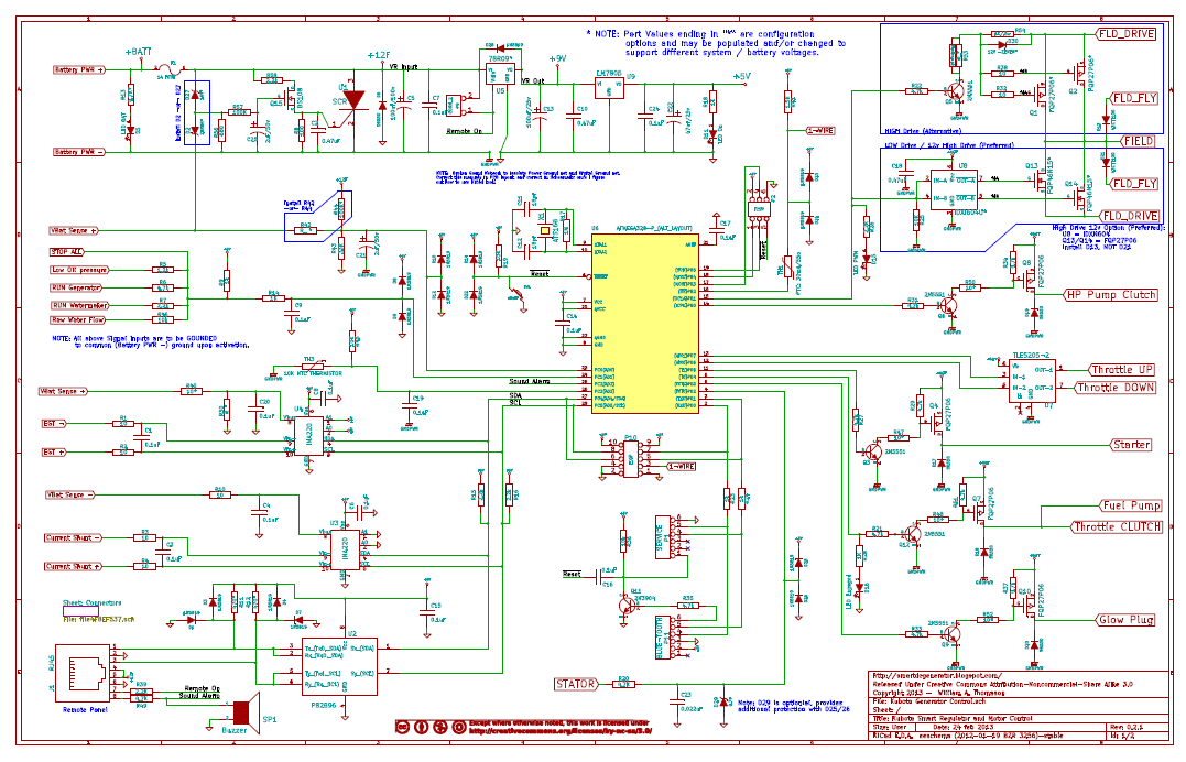
- Support for system voltage of 12v or 24v.
- Support for Battery Voltage of 12, 24, 36, or 48v.
- Support for Field Voltage of 12,24, 26, or 48v. Both High and Low Drive.
- FET temperate monitoring (note, this uses one of the expansion header pins)
- Increased OneWire off-board protection via polyfuses
- Enhanced crowbar - with transient filtering to reduce false triggering
- Changed STARTER from active Low to active to High - perhaps eliminating external relay in many deployments. And also closing the door on a phantom-power path.
- Local buzzer - increased safety before auto-starting
- Added option for RTC - to allow for quite-periods and/or timed auto-starting.
- Optional INA-220's daughter-cards - to improve buildability
- Changed SMD diodes to thruhole - to improve buildability..
- Correct Remote Panel dimensions - to better fit LCD.
- Correct Tx and Rx wiring to Blue-tooth, but it sill needs work to become fully functional.
The .pdf files are located here:
Controller: https://docs.google.com/file/d/0B5GiaoeXCQ3vMlBGU3Y4NkExQ28/edit?usp=sharing
Remote: https://docs.google.com/file/d/0B5GiaoeXCQ3vcG81clVPLTF5cjA/edit?usp=sharing
And this documents the configuration / stuffing options:
https://docs.google.com/file/d/0B5GiaoeXCQ3vUTV3UUwzZllLVUE/edit?usp=sharing

FET Drivers: High Drive, Low Drive . . . This has been a LOT of conversation. So - why not have it your way? By using stuffing options, and changing the driver chip from inverting to normal the design can support High Drive using p-FETs, and Low Drive using n-FETs. And additional benefit is that the GND line is now de-coupled from the logic ground and brought in separately. This should help with noise.
All low drive configs use a good solid FET driver chip and high amp FETs. The High Drive is divided between one using a solid FET driver chip and good amp FETs for 12v fields. For higher field voltages a different drive configuration is used based on an NPN transistor and pull-up. This has the advantage of being able to support higher field voltages, but the disadvantage of slower switching times - and hence some heat displacement in the FETs. But if we recognize that the PWM frequency is actually rather low (490hz) the expected switching power loss calculates to around 2-3w worst case.
Crowbar: I have noticed a few false triggers with the v0.1.3 design, and perhaps that is not unexpected given how noisy a '12v' battery actually can be. In the revised design R57/C25 forms a long time-constant (approx 1s static condition) smoothing filter to reduce sensitivity of transient pulses. Q14 buffers and acts as the voltage comparator / trigger. I selected the FET based partly on its rather narrow range of Vgs turn-on. It is rather crude, but for this use I think a $0.15 FET is OK compared to perhaps $2 for proper voltage comparator (ala op-amp + extras..). This is after all a Last Change thing in case all the traps in the firmware fail.
OneWire: There was no isolation of the Amtel CPU to the nasty outside world on the OneWire bus. An error in connection (accidental grounding, or tying to +5v) will likely destroy that Amtel CPU pin - rendering the one-wire sensors unusable. Adding a couple of polyfuses (TH1 and TH2) take care of isolation and protection.
Added RTC: The firmware supports an auto-start capability based on monitoring battery voltage. However, do you really want the generator starting at 2am? Adding an RTC to the system allows us to enhance the firmware for quite periods, and also forced start times. For example, in a co-gen deployment one might want the generator to auto-start at 6am not only replenishing the batteries but also generator hot water for morning actives. I placed the RTC on the remote board to make it simpler for battery replacement and if one wants this capability with the 0.1.3 design a simple expansion board can be added via the expansion connect on the controller.
Should note: To take advantage of an RTC the firmware will need to be enhanced Currently there is no RTC code in the firmware. . . .
System Voltage vs. Battery Voltage vs. Field Voltage: It is important to recognize there are potentially 3 different, and independent, voltages which may be present:
- Battery Voltage - The House batteries we are trying to charge. The 'voltage' of the Alternator.
- Field Voltage - Often the same as the Battery Voltage, but not always. e.g., deploying a 555 alternator (with its 12v field) to charge a 48v house battery.
- System Voltage - This is the voltage of the engines system and 'accessories': the Starter, Glow Plug, Fuel Pump, and Throttle control motor.
This design revision fully supports a range and combination of Battery and Field voltages from 12v up to 48v. I spent a bit of time trying to support the same range for the System Voltage, and came close. The biggest challenge was the H-bridge for the Throttle Motor.
The Infineon TLE5205 IC is an integrated H-Bridge that deals with all sorts of design problems. Not only doing the voltage switching, but also assuring there is no race conditions during transitions which can stress/burn out the FETs. It also nicely provides a PARK function whereby both motor leads are sent to ground. Plus it is all on one space-saving TO-220 package. I use this part to drive a salvaged automobile throttle control motor - in my case from a Honda cruise control. And it is interesting to note this TLE5205 IC was actually design and sold for this purpose - throttle motor control in automobiles.
But the TLE5205 IC has a Vdd max of 40v, which limits its deployment to a 24v 'system'. I spent some time trying to replicate this function in a design that will support up to 48v systems (Needing a Vdd max of 70v). Though it is possible, the design started to grow VERY large, and getting rather costly.
Though 48v system voltage is solvable today I think there are not really that many 48v starters, fuel pumps, throttle control motors out there. I suspect today most are actually 12v. So, for today I have backed off the design goals and capped system voltage at 24v. Down the road if 48v auto components become common I am sure companies like Infineon will offer integrated driver chips with a higher Vdd. And at that time the design can be revised.
And a note on 0.1.3 boards: They are able to support only 12v system and field voltage. Though they can easily support higher battery voltage.
Today's posting is the 1st draft of a revised design with the goal of easier assembly, wider range of config options, and increased reliability. Over the next few -months?- I will refine this design, and if someone wishes to build a copy of this will take the steps to produce artwork and a PCB package. Truth be told, in my all 12v deployment this board offers no benefit over the 0.3.1 design - with the exception of the OneWire risk (See 0.3.1 Errata document). (And as I do not intend to use Auto-start, the RTC and buzzer are not that critical.)
Comments please. And if anyone is interested to fabing this design, also let me know.
No comments:
Post a Comment